What is an Antenna Tuner or Antenna Tuning Unit ATU
An antenna tuning unit, ATU or antenna tuner is an item consisting of inductors and capacitors that is used to tune an antenna so that it matches the feeder and reduces the SWR.
Antenna tuning units, ATUs or antenna tuners are generally associated with HF transmitters and receivers used for radio communication and other applications. The tuners can be used in a variety of ways: where an antenna element meets the feeder, or within the feeder near to the transmitter.
Their basic purpose is to ensure that the antenna system impedance matches that of the transmitter or receiver and thereby the optimum performance is achieved.
Modern semiconductor transmitters are very susceptible to damage caused by high levels of SWR and therefore they need to be presented with a good impedance match. The ATU / antenna tuner enables this to be achieved and as a result, it is an essential part of many radio communication stations used for broadcast, commercial, military and ham radio.
Older valve or vacuum tube transmitters were more able to withstand the high voltages and current levels that can be caused by the high levels of reflected power. Nevertheless, they still benefitted from the lower loss levels that proper matching provided for any radio communication system.
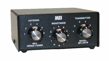
A typical manually adjusted HF amateur band antenna tuner
The need for antenna tuners / antenna tuning units
The antenna tuner or antenna tuning unit is a key element of many ham radio and professional transmitting and receiving HF radio communication stations.
Every antenna, feeder and transmitter and receiver has what is termed a characteristic impedance. For most commercial, professional and ham radio applications the standard is 50 Ω.
It is found that for maximum power transfer, the impedance of the source and load must be the same. If this is not the case, then not all the available power can be transferred.
It is normally quite easy to match the transmitter or receiver to the feeder. Both can be designed to be 50Ω, and this is not an issue.
However the impedance of an antenna can vary very considerably dependent upon its characteristics and the frequency - often there are inductive and capacitive elements to the overall impedance of the antenna.
If there is a mismatch between the feeder and the antenna, then not all the power that is available is able to be transferred. As power cannot just disappear, the power that cannot be transferred has to go somewhere, so it is reflected back along the feeder, setting up voltage and current standing waves.
When these standing waves reach the transmitter, the current and voltage peaks can cause the transmitter output devices to be damaged. To prevent this happening, many transmitters have protection circuitry that reduces the output of the transmitter to a level where the transmitter will not be damaged.
Having a basic understanding of standing waves helps understand the operation of antennas and the need for antenna tuners. It enables the best to be made of any antenna used for any for of radio communication.
Note on Standing Wave Ratio, SWR & VSWR:
Standing waves are often associated with RF feeders, and they are generated when there is a mismatch between the feeder impedance and the load impedance. At th emismatch, power is reflected and the combined voltages and currents of the forward and reflected power form standing waves along the feeder.
An antenna tuner or antenna tuning unit is a network of variable inductors and capacitors that can be altered to counterbalance the effects of the inductive and capacitive elements of the antenna with the aim of making the antenna appear as a resistive load of 50Ω.
There are several circuits that can be used for antenna tuners, each having its own attributes. They vary from simple L configurations with an inductor and a capacitor to other types with more components.
L network antenna tuners: Although there are eight different L networks that can be used in theory, there are four that are used more widely than the rest. As the name might suggest they consist of one element in series with the line, and another down to ground. The L network used for antenna tuners has one of the elements passing from the line to ground as well as the series element as defined in the table below.
Input element to ground
Series Element
Output element to ground
Characteristics
Inductor
Capacitor
- -
High pass impedance step up
- -
Capacitor
Inductor
High pass step down
Capacitor
Inductor
- -
Low pass step up
- -
Inductor
Capacitor
Low pass step down
Normally the low pass option is used for antenna tuners because this provides additional attenuation of the harmonics. A typical impedance step down L network antenna tuner is of the form shown in the diagram below. L network low pass impedance step down antenna tuner circuit
The impedance step up version of the L network antenna tuner is very similar, and has the variable capacitor on the input side, i.e that connected to the receiver or transmitter. L network low pass impedance step up antenna tuner circuit
Often automatic antenna tuners use this form of network with a series switched inductor and switch capacitor which can be directed to either the put of the output dependent upon whether the antenna impedance is above or below the input feeder impedance.
Pi section antenna tuner networks: As the name indicates, these antenna tuner networks have three elements in them - one series element and another element of the other type from the line to ground at both the input and the output.
With a series inductor and two capacitors to ground: one at the input and the other at the output, this configuration forms a low pass filter which provides additional attenuation of harmonics beyond that provided by the transmitter itself.
This format pf matching was widely used as the output tuning for vintage tube of valve based transmitters. Nowadays the Pi network is not popular for use a matching network in antenna tuners because the variable capacitors required in the circuit become large large for the lower frequencies in the HF portion of the spectrum and these are costly. Accordingly this type of tuner is not normally used for ham radio applications as most antenna tuners are designed to cover all the bands between 160 metres and ten metres.
T section network: The T section antenna tuner using a single inductor is able to match a large range of antenna impedances and and introduces little loss. As a result it has been popular at various times. It is actually a high pass configuration, which does not provide any attenuation of harmonics. Also it requires that the variable capacitors are floating, i.e. neither end connected to ground and this does require additional mechanical isolating elements so that the capacitors are mounted not connected to any ground plates, and also special isolating spindle arrangements are needed. This reduces the attractiveness of this type of antenna tuner. T network high pass antenna tuner circuit
SPC Transmatch: The SPC or series parallel capacitor antenna tuner or transmatch uses a configuration that acts as a matching tuner as well as acting as a bandpass filter. This pre-selector element fo this type of antenna tuner is particularly useful on low frequencies where some very strong broadcast signals may overload the front end of the receiver.
In the circuit, there is a central point to which all components are connected. The capacitor C1 provides the variable match to the transmitter. The capacitor C3 provides the variable match to the antenna. The combination of the inductor, L1 and the capacitor C2 provide a tank circuit that is tuned tot he resonance of the required frequency and thereby enables out of band signals to be rejected.
The could is shown as switched here, although a continuously variable one can be used, although they are much more expensive. The variability of the coil enables the band pass filter to be widened or narrowed and ensures that the C2 / C3 combination is able to match the antenna whilst also tuning to the frequency of operation for the two way radio communication link.
Typical SPC network antenna tuner configuration
There are many other formats for antenna tuners, but the ones described show some of the more popular types.
Location of antenna tuner
The ideal position for the location of the antenna tuner is at the point where the antenna is fed by the feeder. In this way, the antenna can be matched to the antenna and all the way through the system there are good matches, and the levels of SWR are low.
Antenna tuner located at feed point of the antenna
Unfortunately it is not always easy to locate the antenna tuner at the point where the antenna is fed. This may be some distance way from the transmitter, and could even be in a position that would not be accessible.
Under these circumstances, the antenna tuner can be located close to the transmitter, even when coaxial feeder is used to connect the tuner to the antenna.
It is a common misconception that a high standing wave ratio itself causes loss. This is not true. When a high standing wave ratio exists, this results from power being reflected back along the feeder as a result of a mismatch. When it enters the antenna tuner, it is reflected back along the feeder to the antenna where a proportion is radiated and some reflected back along the feeder again.
Even with an SWR of 2:1, only 11% of power is reflected and 89% is radiated.
Antenna tuner located close to the transmitter
Open wire feeder is often used for antennas where there are high levels of reflected power in the feeder. As the losses in open wire feeder are very low, this is not a problem. For coaxial cable, losses are higher, but if high quality low loss cable is used, then the overall losses are acceptable.
Provided the coaxial cable can operate with the higher voltage and current levels caused by the high SWR, then this is quite acceptable. The main issue is to prevent the transmitter seeing the high SWR as this might damage the output, or the protection circuitry will reduce the power output.
Accordingly it is quite acceptable to use an antenna tuner or antenna tuning unit close to the transmitter and not at the feed point of the antenna.
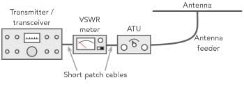
It is worth placing a VSWR meter in the line to monitor the actual level of standing waves seen by the transmitter. Note: a separate meter may not be required if one is incorporated into the transmitter, unless it is more convenient to monitor the level separately.
Incorporating an ATU into a transmitter feed system with a VSWR meter
Antenna tuners are essential items of equipment for any HF radio communications system. Although the principles hold good for VHF and above, the types of antennas and techniques used mean that antenna tuners are not normally required.
For HF, antenna tuners enable the maximum amount of power to be transferred into the antenna, whether a low power transmitter is used of a high power one. Accordingly antenna tuners are widely used for all forms of two way radio communication as well as for broadcasting, monitoring and a variety of other applications for HF radio.
Fact of the day: On 28th April 1686, the first volume of Isaac Newton\'s "Principia Mathamatic" was published.
Quote:No one is born to hate another person because of the colour of his skin; people learn to hate; they can be taught to love, because love comes more naturally to the human heart. Nelson Mandela
Point to ponder: Jack Kilby\'s first integrated circuit contained just one transistor. Today the Intel Itanium 2 contains 410 million.